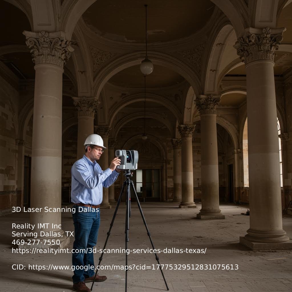
Turning 3D laser scans into AutoCAD files starts with accurate point cloud data. That means scanning the site with LiDAR or similar tools to capture millions of spatial measurements. For teams that rely on exact measurements 3D building scanning Dallas TX ensures your team has the accurate building data needed to move forward with confidence.. In Dallas, teams use this for commercial renovations, preserving historic buildings, and upgrading facilities—anywhere you need to document what’s actually there, not just what the blueprints show.
After scanning, the raw data—usually in formats like .e57 or .las—gets registered and cleaned. This step aligns multiple scans, removes noise, and ensures everything matches the right coordinate system. Rushing here can lead to errors. Misaligned scans create inaccurate models, which can lead to bad construction decisions.
Next, the cleaned point cloud goes into software like ReCap or AutoCAD. Technicians trace over the cloud to build 2D floor plans, elevations, or full 3D models. It’s not automatic. Skilled CAD technicians must interpret the data. They need to tell the difference between a pipe and a shadow, or spot a bowed wall and show that in the model.
Why does this matter? Design and engineering teams rely on these files. If the AutoCAD drawing is even an inch off, it can mess up prefabrication, clash checks, or permit approvals. That’s why you need teams who know both the scanning tools and the CAD standards used in AEC work.
Converting 3D laser scan data into AutoCAD files isn’t just about clean visuals. It affects how accurately the design team works, how well drawings meet building codes, and how much rework gets avoided. In complex renovation jobs, small CAD errors can cause real construction issues—walls that don’t match, misaligned systems, and costly delays.
In Dallas, teams often scan office towers, warehouses, hospitals, and historic buildings. That data becomes 2D floor plans, elevations, and 3D models in AutoCAD. But if the technician misses key features or rushes the process, the drawings won’t reflect reality. Then architects and engineers end up designing on top of bad data.
Accurate AutoCAD files must reflect real field conditions—odd wall angles, unusual ceiling heights, structural shifts. That takes skilled technicians who know how to read point cloud data and model it correctly. It’s not just about running software. The better the CAD output, the easier it is to coordinate trades, get permits, and avoid construction issues.
It takes more time at the start. But skipping accuracy checks or rushing the model leads to bigger problems later. And those always cost more to fix.
Start by checking how well the AutoCAD file matches real-world measurements. If a wall should be 12 feet long, the CAD file shouldn’t say 11.92 or 12.15. That kind of drift can cause problems, especially in structural retrofits or prefabrication. Accuracy should meet project tolerances—usually within 1/8 inch for architectural work. Poor scanning or bad point cloud registration can throw this off. Always compare the CAD file with known site dimensions or control points to catch mistakes early.
Edges, surfaces, and corners from the 3D scan need to convert cleanly into the AutoCAD model. Watch for overlapping lines, broken polylines, or misaligned surfaces. These issues often go unnoticed until someone uses the file for modeling or fabrication. If the geometry is messy, tools like Revit or CAM software may not work properly. Use section cuts and 3D views to check for problems before sharing the file. Plan time for geometry cleanup after conversion.
AutoCAD files from 3D scans need a clear, consistent layer setup. Put walls, doors, plumbing, and electrical elements on separate, labeled layers. Without this, the file becomes hard to use. Follow project standards or industry rules like AIA guidelines. Some scan-to-CAD services skip this and lump everything into generic layers. That makes it harder for architects and engineers to work with the file.
CAD files from point clouds often include too much detail. Extra polylines, unused blocks, and random layers increase file size and slow things down. That’s a problem when teams need to load the file into BIM tools. Clean up the geometry, remove unused items, and lower the resolution where possible. A lean file opens faster, runs smoother, and keeps the important stuff. Skipping this step can slow down the whole project.
The CAD file should keep key features from the scan—like textures, material edges, and structural quirks. If a beam is bowed or a floor slopes, that should show in the drawing. Many conversions skip these to save time. But in renovation, safety checks, or historic work, those details matter. This is even more true in older buildings where nothing is square. Leaving out these features can cause design errors or expensive fixes later.
When converting 3D scan data into AutoCAD files, accuracy is the baseline. In Dallas, where 3D laser scanning supports projects from hospitals to historic buildings, expectations stay high. The CAD geometry must match real-world conditions with tight tolerances. For structural and MEP work, the standard is usually within 1/4 inch or about 6mm. Architectural elements like walls, doors, and windows allow slightly more variation, but not much.
One common mistake is relying too much on automatic mesh-to-CAD tools without checking the results. These tools can misread complex areas, especially in older buildings with uneven surfaces. Another issue is over-simplifying—flattening a 3D wall that’s actually bowed or out-of-plumb. That might work in early design but causes problems during construction or prefabrication.
Validation starts by comparing key dimensions from the scan with known control points or existing drawings. If those aren’t available, survey benchmarks or total station data help verify the model. In AutoCAD, this means checking that the geometry matches the scan point cloud and that all critical dimensions—wall thicknesses, slab elevations, pipe offsets—fall within limits. It’s not just about matching shapes. Everything must fit where it belongs.
If tolerances fall short, the risks climb fast. Misaligned ductwork, misfit structural steel, or wrong slab elevations can lead to change orders, delays, and rework. That’s why every AutoCAD file from a scan needs a full check—line by line if needed—before it’s used for design, permitting, or fabrication.

When converting 3D laser scans into AutoCAD files, many people overlook how the layers are set up. But if you use these files for design, coordination, or facility work, the layer structure matters. In Dallas, where firms use 3D scanning for everything from historic renovations to large commercial builds, the AutoCAD output needs to be more than accurate. It needs to be practical.
A clean CAD file uses clear, standard layers—walls, doors, windows, electrical, HVAC, structural elements, and more. That helps teams like architects, MEP engineers, and contractors find what they need without digging through clutter. If everything lands on one or two generic layers like “Layer 0” or “Scan Data,” it slows everything down. You can’t run clash checks, submit for permits, or even print cleanly.
Follow standard naming rules, like those from the National CAD Standard (NCS) or proven company templates. Good scan-to-CAD providers in Dallas should already do this. If not, you’ll waste hours fixing layers or risk mistakes during edits.
This setup also makes updates easier. If you return six months later to revise an as-built or update a mechanical run, smart layers let you add new data without redoing the whole file. It saves time and keeps the team on the same page.
When converting 3D laser scans into AutoCAD files, the output needs more than accurate geometry. Metadata, dimensions, and formatting matter too—especially for teams using those files in architecture, engineering, or asset tracking. In places like Dallas, where 3D scanning supports many commercial and industrial projects, missing or messy data can slow everything down.
Start with metadata. Each component in the drawing should include useful info like material type, system ID, floor level, or manufacturer. If that data isn’t in the file, someone has to hunt it down later. That wastes time and increases the risk of mistakes during construction or renovation.
Next, look at dimensioning. AutoCAD files from point clouds should include verified dimensions that match the real site. If dimensions are missing or off, engineers and contractors won’t trust the file. That leads to rework—or worse, design errors that show up when materials arrive.
Tags and layer names also matter. They should follow consistent, project-specific rules. Without that, it’s tough to separate systems like MEP from structural elements. And if the file feeds into a BIM workflow, clean formatting is even more important. BIM-ready CAD files should be organized and include data that Revit or similar tools can read without extra cleanup.
Here is why this matters: if the AutoCAD file lacks structured data, clear annotations, or BIM-ready formatting, it slows everything down. Someone else has to fix it, which adds time and cost.
When converting 3D scan data into AutoCAD files, your method affects accuracy, speed, and rework. Manual drafting still plays a role, especially with complex or irregular scans. A trained CAD technician can spot details software might miss. But it’s slow, depends on experience, and invites human error, especially with dense point clouds or low-quality scans.
Semi-automated tools speed things up. They extract basic geometry like walls, floors, and pipes. These tools work well in clean, repetitive spaces. Still, someone must check the output and confirm the dimensions. Skipping that step can cause errors in construction documents or coordination models, leading to delays and change orders.
AI tools are gaining ground, especially on large commercial or industrial sites in places like Dallas where time and precision matter. These systems can label objects, create floor plans, and build 3D models in AutoCAD formats. But they miss things. Mislabeling or skipping small details like conduit runs or wall thicknesses still happens. A technician must review the results. Otherwise, you're taking a big risk. Here is why: errors in MEP coordination or structural retrofits can be costly.
In Dallas, 3D laser scanning helps create AutoCAD files that reflect real-world conditions. These files support design and engineering work when original drawings are missing or outdated. Architects use them to produce as-builts before starting renovation or reuse projects. It’s faster than measuring by hand, and the point cloud data captures walls, windows, and structural elements down to the inch—or even millimeter.
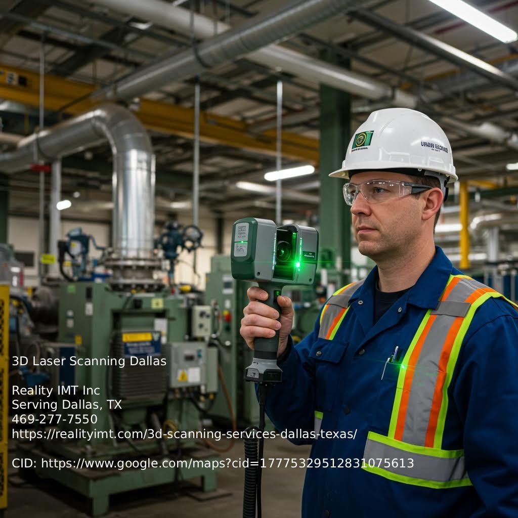
In MEP engineering, scan-to-CAD maps out mechanical rooms, ductwork, piping, and electrical systems. Engineers use the 3D layout to plan upgrades without hitting existing infrastructure. This matters in older buildings with incomplete documentation. One common mistake is skipping verification—assuming the scan data is correct without checking alignment. That can lead to AutoCAD files that look right but don’t match field conditions.
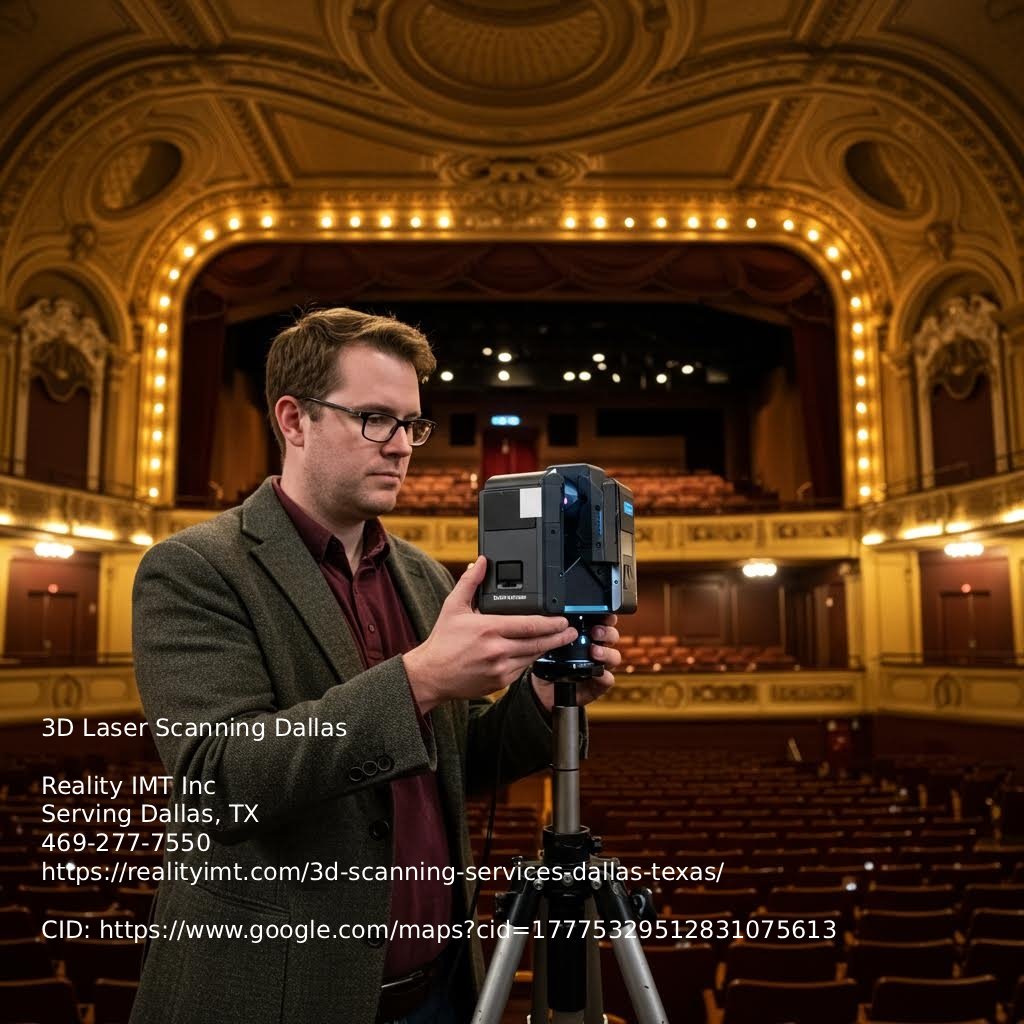
Commercial real estate developers use scan data to create floor plans and layouts for leasing and planning. AutoCAD files show square footage, ceiling heights, and column locations. That’s helpful for tenant fit-outs and code checks. In historic preservation, scan-to-CAD captures complex details—like ornamentation or uneven walls—that are hard to measure by hand. It also creates a digital record before restoration, which helps with documentation and approvals.
Across all these uses, accuracy matters. If the AutoCAD file doesn’t match the site, it causes delays, rework, and safety risks. Here is why quality control during scan-to-CAD matters—it keeps projects on track.
After converting a 3D laser scan into an AutoCAD file, the next step is making sure the file works for real-world design, coordination, and construction. This is where quality checks matter. If you're using scan-to-CAD services in Dallas for commercial or industrial projects, you need a clear QA process before using those files in design workflows.
Start with a checklist. It doesn’t have to be complex, but it should cover layer organization, line weights, block naming, and whether all key dimensions from the scan are accurate. Small issues like inconsistent layer names can disrupt coordination between architecture and MEP teams.
Validation tools help too. AutoCAD includes features that catch geometry issues like overlapping lines or unclosed polylines. These aren’t just visual problems. They can trigger errors when importing files into BIM platforms or CNC machines. Some teams also compare the original point cloud with the final drawing to confirm that key dimensions stayed intact during tracing.
Third-party review adds another level of protection. On complex projects—such as hospitals, industrial plants, or historic buildings—an extra review can catch mistakes your team missed. Whether it’s a QC consultant or someone from another department, the goal stays the same: make sure the AutoCAD file matches the scanned structure and works across all project stages.

If you're using 3D laser scanning in Dallas to create AutoCAD files, accuracy is key. These drawings support construction, renovation, MEP coordination, and facility use. Start by checking the provider’s technical skills. Do they know how to read point cloud data? Can they tell the difference between structural, architectural, and mechanical parts? Ask for sample DWG files. Look for clean layers, correct line weights, and clear naming. Poor CAD work can lead to costly mistakes.
Next, consider turnaround time. Some providers deliver simple 2D plans in a few days, while detailed 3D models take longer. But speed isn’t everything. What counts is getting files that don’t need fixing. A solid provider also understands different project needs. Historic work often needs more detail than commercial projects. MEP engineers focus on pipe size and routing. Architects care about wall alignment and door placement. The right team gets these differences and adjusts.
Also, ask how long they’ve worked in this space. Experience with commercial, industrial, or historic buildings in Dallas helps. Local materials and methods vary, and someone who’s only done homes might miss key details in an old warehouse. One more thing—check their QA process. Do they compare CAD files to scan data? Do they flag unclear areas? These steps help you get drawings you can trust.
When converting 3D laser scan data into AutoCAD files, accuracy is everything. If the CAD drawings don’t match real-world conditions, things can go wrong fast. Misaligned walls, wrong elevations, and missing elements can cause delays, rework, and extra costs. That’s why checking the quality of AutoCAD files from 3D scans matters.
What should you check? Geometric accuracy, layer setup, clear annotations, and file usability. Do the dimensions match the site? Are walls, doors, and MEP systems in the right layers? Can your team use the file in Revit or another CAD program without hours of cleanup? These details affect how quickly your team can work and how much you can trust the drawings.
In Dallas, teams use 3D scanning services every day to get accurate AutoCAD files. Whether it’s a downtown office renovation or a mechanical update in a plant, good 2D and 3D CAD files save time and cut risk.
Working on a project that needs accurate as-built drawings? Don’t guess. Ask for a demo or book a consultation. We’ll show you what a clean, usable AutoCAD file looks like—and how to avoid mistakes that slow you down.